|
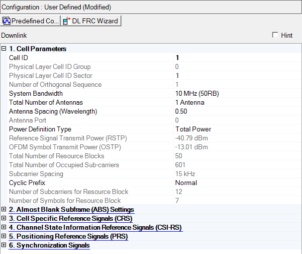
1. Cell Parameters |
|---|
| System Bandwidth |
| Antenna Port |
| Power Definition Type |
| Reference Signal Transmit Power (RSTP) |
| OFDM Symbol Transmit Power (OSTP) |
Range: 0 to 503
Default: 1
Enter a value for the Cell ID. The software sets the values in the and cells based on the entry. Cell ID = [(3 x Physical Cell ID Group) + Physical Cell ID Sector]. See 3GPP TS 36.211.
This property is also available in the Carrier Aggregation node.
Range: 0 to 167
Default: 0
The software sets this value based on the entry. Cell ID = [(3 x Physical Cell ID Group) + Physical Cell ID Sector]. (See 3GPP TS 36.211.)
Choice: 0 | 1 | 2
Default: 0
The software sets this value based on the entry. Cell ID = [(3 x Physical Cell ID Group) + Physical Cell ID Sector]. (See 3GPP TS 36.211.)
Range: 0 to 2
When you set the value in the Physical Layer Cell ID Sector cell, the software sets the Number of Orthogonal Sequence to the corresponding value. (See 3GPP TS 36.211.)
Choice: 1.4 MHz (6RB) | 3 MHz (15RB) | 5 MHz (25RB) | 10 MHz (50RB) | 15 MHz (75RB) | 20 MHz (100RB)
Default: 5 MHz (25RB)
Double-click or use the drop-down menu to set the system bandwidth and number of Resource Blocks (RB). When you select a system bandwidth, the software automatically adjusts the value in the cell and the cell.
When the System Bandwidth is decreased, the DL-SCH Tx Sequence window's RB size, and some of the other data channel's settings, are reconfigured, similar to when a Predefined Configuration is executed. But, when the System Bandwidth is increased, no change to the DL-SCH Tx Sequence window's RB size, or the other data channel's settings occurs.
Refer to 3GPP TS 36.211.
Choice: 1 Antenna | 2 Antennas | 4 Antennas | 8 Antennas
Default: 1 Antenna
Specify the total number of base station antennas.
For multiple signal generator configurations, set the Channel State parameter in the Fading section of the Carrier node to to make this cell active. When the channel state is off, you must change the number of signal generators (for example, use a Quick Setup) to change the number of BS antennas.
This parameter indicates the total number of physical antenna port configuration used for downlink transmission in this cell.
Total number of Antennas and Number of CRS Antenna Ports determines the resource elements that are reserved for Cell Specific reference signals.
Total number of Antennas and Number of CRS Antenna Ports are different parameters and are available to set respectively.
Refer to 3GPP TS 36.211 and 36.311.
Range: 0.00–100
Default: 0.5
Enter a value that specifies the distance between the antennas. The value is specified in wavelengths units of the center frequency for the corresponding Component Carrier. Use this setting when generating a beamforming signal.
Choice: 0 | 1 | 2 | 3 | 4 | 5 | 6 | 7
Default: 0
In multi-antenna configurations, specify the antenna to be used for transmitting the downlink signal. The available selections are determined by the setting.
Refer to 3GPP TS 36.211.
Choice: Total Power | RSTP
Default: Total Power
Double-click or use the drop-down menu to select the power definition type for the primary cell.
The power definition type for secondary cells is automatically set same type of the primary cell and set the value as read-only.
In multiple carrier case, Power Definition Type parameter in each carrier should be same.
If Total Power is selected, power reference is Amplitude parameter on Instrument node. In single/multiple carrier and Total Power case, RSTP and OSTP are automatically calculated by Amplitude parameter on Instrument node, Power parameter on Component Carrier and each carrier signal settings.
If RSTP is selected, power reference is RSTP. In single/multiple carrier and RSTP case, Amplitude parameter on Instrument node, Power parameter on Component Carrier and OSTP are automatically calculated by RSTP and each carrier signal settings. In this case, Power parameter on Component Carrier is set read-only.
If uplink and downlink carriers are mixed as multiple carrier, correct RSTP calculation is not available.
Range: -15.00 to -144.00 dBm
Default: -40.79 dBm
Enter the Reference Signal Transmit Power in dBm, when the Power Definition Type is RSTP. Otherwise displays the Reference Signal Transmit Power in dBm and the value is updated after generation.
In the case Power Definition Type is Total Power, RSTP is automatically calculated by Amplitude parameter in Instrument, Power parameter in Component Carrier and each carrier signal settings.
In the case Power Definition Type is RSTP, Amplitude parameter in Instrument and Power parameter in the Component Carrier is automatically calculated and set the value as read-only.
Available setting range and step depends on hardware.
See 3GPP TS 36.141 for more information.
Display the Downlink OFDM Symbol Transmit Power in dBm. This parameter is set by the software.
For detailed information about OSTP, refer to 3GPP TS 36.141.
The value in this cell is set by the software based on the setting.
The value in this cell is set by the software based on the setting. The center subcarrier is not used for downlink transmission, so the number of transmitted subcarriers is one less than the number of occupied subcarriers.
Default: 15 kHz
Displays the subcarrier spacing for the downlink. Only 15 kHz spacing is available in this release.
Choice: Normal | Extended
Default: Normal
Double-click or use the drop-down menu to select a or cyclic prefix. The software sets the based on the cyclic prefix selection.
Default: 12
Displays the number of consecutive subcarriers in a downlink resource block.
Default: 7 for Cyclic Prefix; 6 for Cyclic Prefix
Displays the number of consecutive OFDM symbols in a downlink slot.